Principle of Mud gas separator for oil well drilling
We Selecting mud gas separators to consider factors including but not limited to the followings. Mudflow rate of whole well drilling, possible toxic gas content, working site condition. To operate degassers properly we need to know the degasser working principle, and more tips blow, too.
Mud gas separator principle
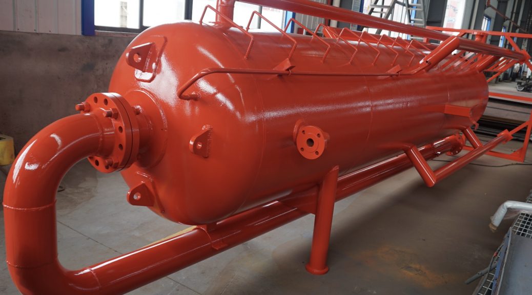
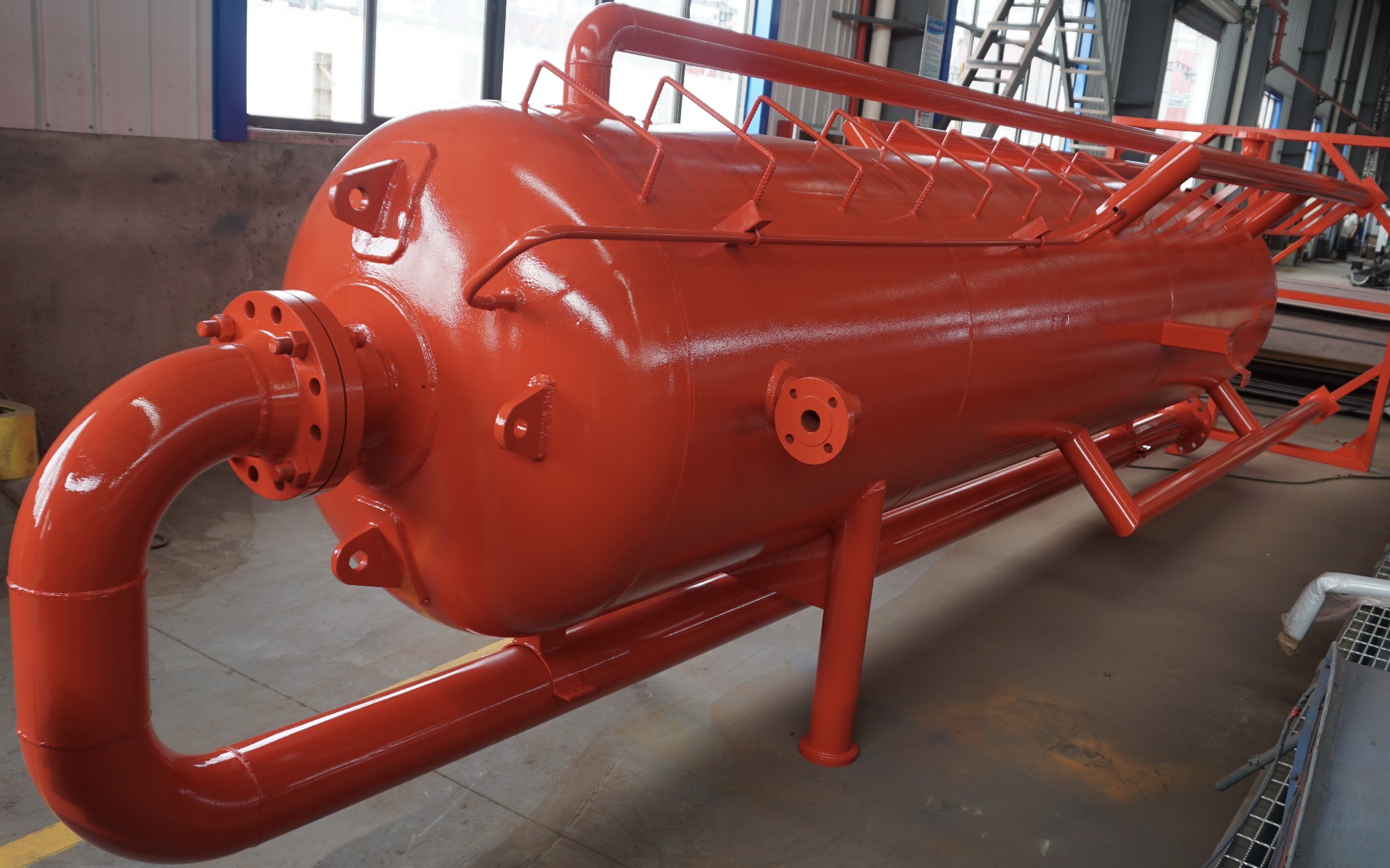
We’ll talk about work principle and design principle of mud gas separator. Such gas separator is also called poor boy degasser sometimes. Since we mainly use it to get rid of invading gas during whole well drilling. There are horizontal or vertical type. But a Vertical separator is normally for high fluid throughput, while a horizontal separator provides a longer retention time and superior gas separating capacity. Internal design and configuration (e.g. blast chamber, baffle plate etc.) govern the individual efficiency of the equipment.
Drilling fluids from downstream of chokes flow into mud gas separator by hard piping, under the collision or sudden drop down by baffle plate and from vessel top the invading gas or bubbles will break and let gas go flow away via vent line.
The mud gas separators should be able to handle a high proportion of mud solids and may experience hydrate plugging as a result of gas expansion through the choke. Designs based on conventional process practice, involving a float controlled liquid dump valve and a control valve to regulate gas pressure are not suitable because of the accentuated risk of malfunction due to plugging and the consequent need to provide a relief valve which itself may plug. Mud gas separator designs should therefore be based only on a liquid seal system matched to an adequate gas vent.
Users should monitor the operating limits of a mud gas separator by observing the differential pressure in the separator. A low range pressure gauge should be installed, readily visible from the choke control position. A remote pressure transmitter may be used for this purpose but should be capable of operation without dependence on rig air supply or rig electrical power. Where remote gauges are installed, a back-up gauge on the separator vessel itself is still recommended.
Details to consider for degassing process
We all know the importance of degassing during well drilling. It’s critical to keep working site safe away from block out or any fire/explosion. So besides above issues, we need to consider followings when design degassing system.
Liquid Throughputs
The volumetric flow capacity of the system should be based on an adequate gravitational rate from the separator. A typical liquid capacity of 6 barrels per minute of 12 pounds per gallons drilling fluid of average viscosity is a guide for vertical mud gas separator.
Liquid seal design
The liquid seal ensures that separated gas vents safely without breaking through to the mud tanks.The seal may be in the form of an external U-tube or may be based on a dip tube extending into a tank, usually the trip tank. Operators must monitor the liquid seal hydrostatic pressure against the backpressure of the gas vent line in the mud gas separator. It may be integrated as part of an instrumentation control system for the whole system.
Anti-Siphon Line
If we design the liquid seal on a U-tube type, we need to fit an independent vent pipe, preferably 6 inches nominal diameter or larger, at the highest point of the pipe work to avoid siphon effects. And as a back-up to dispose of gas carried through the U tube liquid seal. The secondary vent need not extend to the top of the derrick. We should never tie it onto the primary vent.
Relief lines
All surface gas handling systems should have a means of diverting the flow from the choke and kill manifold through overboard relief lines and isolating the mud gas separator. In a blow-out situation, this may be the last resort to allow the evacuation of personnel from the drilling rig. The pressure rating of the piping and valves on overboard lines should not be less than the pressure of choke and kill manifold buffer vessel. The lines should be as straight as possible with minimum bends to the safe area
Necessary instrumentation for degasser
We should fit the degasser with temperature and pressure sensors to provide a remote read-out on a panel in the driller’s cabin. Local pressure gauge to the separator vessel is optional. A remote logic control system should be available. The drillers bypass the degasser at the buffet tank when the system capacity or liquid seal may be exceeded. Visual and/or audible alarm to alert the driller is optional.
Isolation valves should have pneumatic actuators with air reservoirs to provide power in an emergency situation. We operate a control system from the driller’s cabin, wherea mimic board displays their location and status
If the driller decided to activate the bypass operation, the system logic should then isolates the gas separator by closing the valves between the vessel and the buffer tank. The valve control system ensures that one flow path is always open.
The driller pre-sets which valve is to be open at any particular time depending on factors such as wind direction and proximity to hazardous operations. The relief lines terminate in locations with lower risk to personnel, i.e. remote away from the accommodation, muster area etc.
These are some practical guidance or rules for degassing system or a degasser design. Many information and technical datasheet have been verified and proved. Under theoretical analysis as well as decades of drilling experience, we get present principle and regulations . If you do need further assistance or reference, please feel free to contact Aipu solids control.
Note: Some content of this post is from a publication by Peter Lee, Executive Petroleum Engineer,
© State of Queensland, 2016